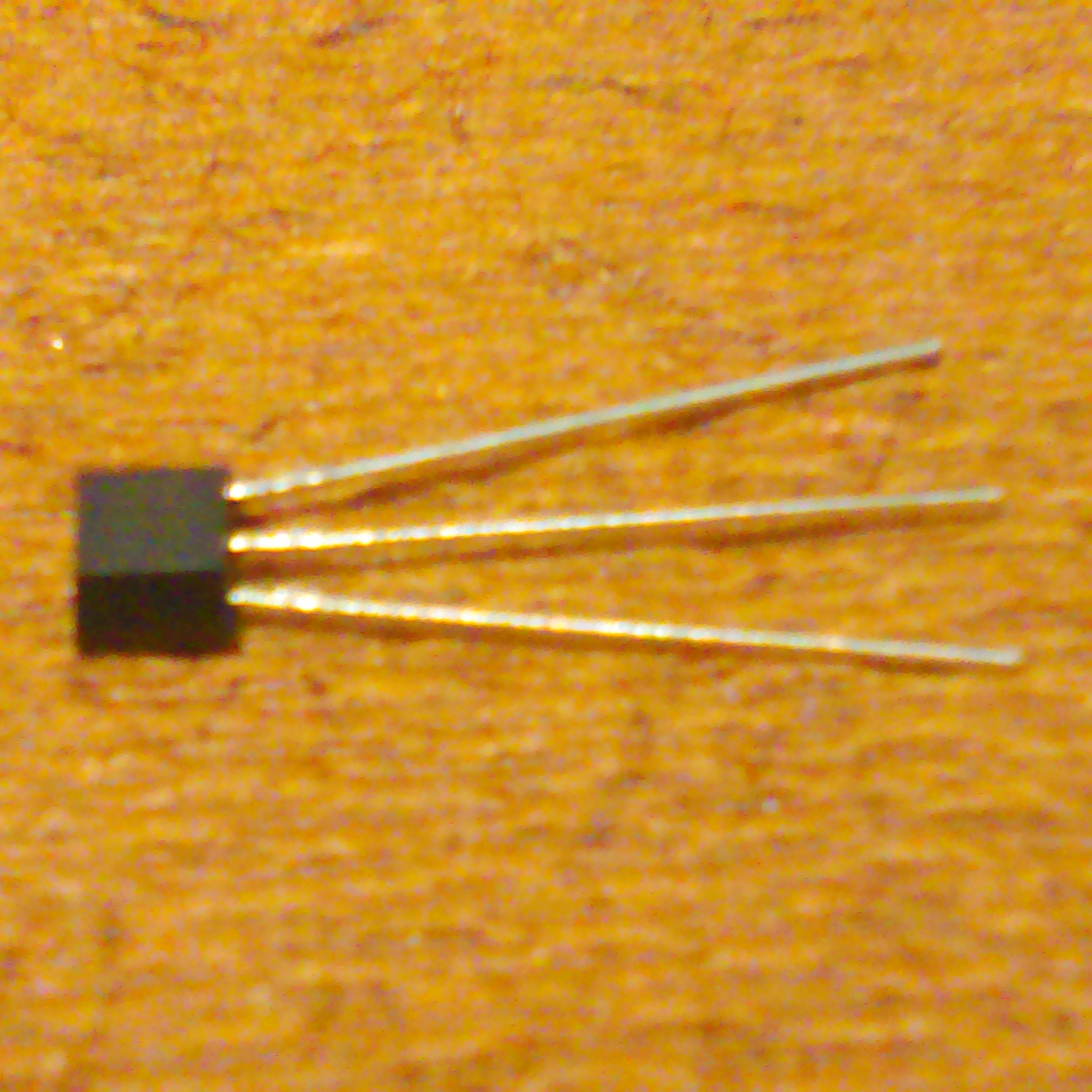
Description
Note: Looking at the black head of the Hall Effect Sensor, the side that has a writing of 460S is the top face and the other side is the bottom face. Place the Hall Effect Sensor so that the bottom face is against the table and top face is the face that you can see. Looking down at the top face with the pins facing towards you. The first pin is the Vs, the second pin is the Ground (-) and the third pin is the Output.
The output current flows when the South pole is facing the top face and remains on. It then turns off when the North pole is facing the same top face.
Notes:
1) Do not exceed the maximum limits of the sensor. Use a resistor or other components when needed.
2) For applications requiring a higher output current greater than the maximum output current rating, use an amplifier such as a transistor to carry that amount of current.
3) For DC Motor applications, remember to use a diode to drain the spike voltage that occurs when the current is automatically turned off.
Basic Specs
Supply Voltage minimum: 3 V
Supply Voltage maximum: 24 V
Magnetic Flux Density: Unlimited.
Supply Current typical: 3.5 mA
Supply Current max: 8 mA
Output Current max: 20 mA
Operating Temp: -40F to 302 F
Maximum Junction Temp: 260 F
Storage Temp: -40 F to 320 F
Operating point min: 5 Gauss
Operating point max: 55 Gauss
Release point min: -55 Gauss
Release point max: -5 Gauss
Differential min: 40 Gauss
Differential max: 80 Gauss
Notes:
1) The device has a safety feature. It will shut down after the output current is over the output current 90mA for 160us (typically). The device will re-start up operating after resetting the supply voltage.
2) Magnetic characteristics are for design information, which will vary with supply voltage, operating temperature and after soldering.
FEATURES/BENEFITS
- Built-in voltage overshoot protection.
- Built-in power reverse protection.
- Fastest response time in its class
- Output short circuit protection.
- 3V to 24V DC operation voltage.
- High Sensitivity.
- No-Chopper-Stabilization providing a clean, stable output signal and a faster latch response time when compared to competitive high sensitivity Hall-effect latching sensor ICs which do use chopper stabilization.
- Latching magnetics.
- Wide operating voltage range.
- Open drain pre-driver.
- Lead Free Finish/RoHS Compliant. EU Directive 2002/95/EC (RoHS). All applicable RoHS exemptions applied.
- Easy to use.
- Durable.
- Safe.
- Well designed.
- Easy to install.
TYPICAL APPLICATIONS
- Brush-less DC Motor Commutation.
- Speed and RPM Detection.
- Tachometer, counter pickup.
- Robotics controls.
- Consumer and industrial position sensor.
- Flow meters.
- Flow rate sensing for appliances.
- Electronic window lift.
- Anti-pinch power window system.
- Vehicle convertible roof position.
- Medical equipment.
- Ideal for making electromagnets.
- LED blinkers and pulsations.
- Relays.
- Electronic communication.
- Inductors.
- Radio frequency.
- Solenoids.
- Small Transformers.
- Motors
- Timers.
- Automotive.
- Environmental Solutions.


Reviews
There are no reviews yet.