Description
NB: Use pure DC Voltages (like Batteries) for the Regulator/ Converter.
DC Input Voltage range: 1.8VDC to 5VDC
Constant Output Voltage: 5VDC
Output Current for 1.8V input: 500mA
Minimum output current for 3.7V input: 1000mA.
Weight: 0.106 ounce (3 g)
PCB dimensions: (1.1 X 0.9 X 0.08) inches
DESCRIPTION AND NOTES
This “Step Up/Boost Voltage Converter” operates over the DC input voltage range from (1.8V-5V) and produces a constant output voltage of 5VDC.
INPUT SIDE:
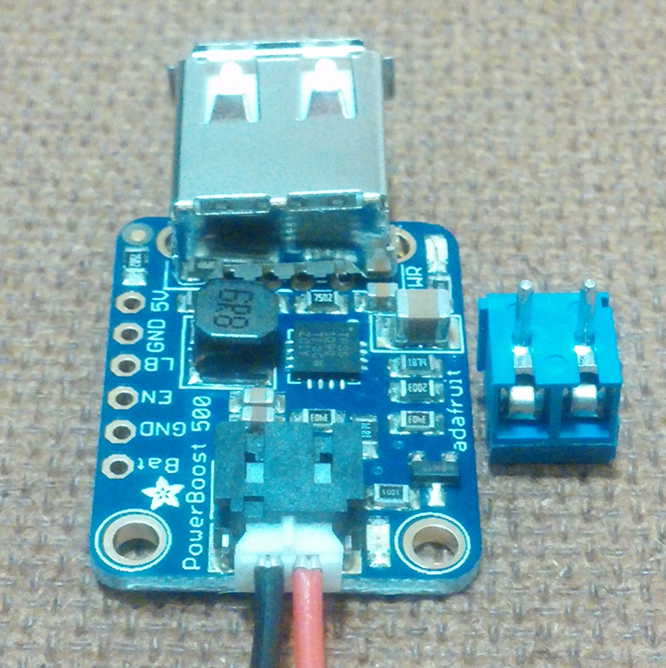
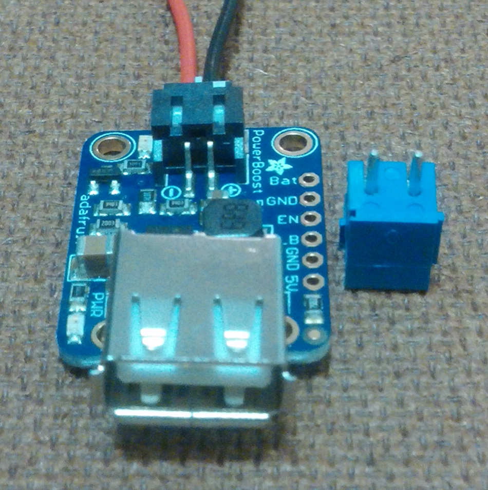
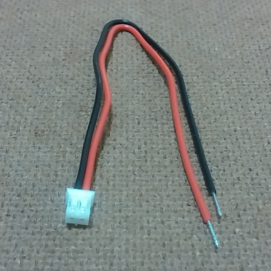
This converter comes with a “JST-PH 2-Pin SMT Right Angle Connector” (black in color) soldered in the PCB for better connection to the input. Connect the JST 2-pin cable (white head with red and black wires) to the “JST-PH 2-Pin SMT Right Angle Connector”. Then connect your red wire to the (+) positive input voltage and the black wire to the (-) negative input voltage. Note that there is a (+) positive and (-) negative sign on the Vin part on the PCB Boost Converter. (+) positive for your input positive voltage and (-) negative for your input negative voltage.
OUTPUT SIDE:
The converter also comes with a loose “USB A jack” that can be connected to the output to power any USB device. Note that you do not have to use the “USB A jack” for the output. You could just use a “2-pin 3.5mm terminal block” (blue in color) for the output. There are two golden holes in front of the 4 golden holes (where the USB 4 pins go into). Insert the “2-pin 3.5mm terminal block” there. Then put in your output positive and negative wires into the “2-pin 3.5mm terminal block”. There are two screws on top of the “2-pin 3.5mm terminal block” which you could use to tighten the voltage wires firmly for a fit connection. Note you could also just insert two wires (22AWG preferably) into those two holes instead of the “2-pin 3.5mm terminal block”. There is a (+) positive and (-) negative sign on the output part. (+) positive for your output positive voltage and (-) negative for your output negative voltage.
You could solder the “2-pin 3.5mm terminal block”, “USB A jack “, or wire (22AWG preferably) for better electrical connection.
NOTES:
The green light LED shows that the converter is receiving input power.
The red light LED indicates low input voltage below 3.2V.
FEATURES
- Synchronous operation. Could disconnect the output completely by connecting the EN pin to ground. This will completely turn off the output.
- Synchronous Conversion.
- 700 KHz high frequency operation.
- 2A (2.5 peak limiting) internal switch. Could get 500mA from as low as 1.8V input and at least 1000mA from 3.7V input.
- On-Board 500mA charge-rate ‘Apple/iOS’ data resistors. Solder in the included USB connector and you can plug in any iPhone or iPod for 500mA charge rate.
- Full breakout for battery in, control pins and power out.
- 90% operating efficiency. Low quiescent current; 5mA when enabled and power LED is on. 20uA when disabled (power and low battery LED are off).
- Perfect Universal power supply for all portable projects.
- Takes input fluctuating voltage and produces output constant voltage.
- Compact and Portable Design.
- Power-On indication LED.
- Low-Voltage indication LED.
- Long life.
- Easy to use.
- Durable.
- Safe.
- Well designed.
- Easy to install.
TYPICAL APPLICATIONS
- Robotics
- Arduino project.
- Raspberry Pi.
- Beagle Bone.
- Single-board-computer applications.
- Automotive.
- Environmental Solutions.
- General.
- Laboratory.


Reviews
There are no reviews yet.